› RC BOATING › YACHTING › DF65’s & DF95’s › Tips, Tricks and Settings › SET-UP OF FLYSKY FS-i6X TRANSMITTER (Tx) AND FS-iA6B RECEIVER FOR RACING YACHTS
Tagged: Tx
- This topic has 2 replies, 2 voices, and was last updated September 28, 2022 at 4:23 pm by
Admiral.
-
AuthorPosts
-
-
28 September 2022 at 15:39 #12385
Set-up of FlySky FS-i6/FS-i6X Transmitter (Tx) and FS-iA6B Receiver (Rx) for DF Racing Yachts (David Flakelar)
- These notes are written to help the beginner set-up the FlySky Tx/Rx system to operate with the DF65. There are also a few tips in an appendix that have nothing to do with the FlySky system but may provide some useful background.
- The FlySky FS-i6 system operates under the Digital Proportional Protocol using an Automatic Frequency Hopping Digital System. It is a pulse digital system on carrier frequencies unique to a particular transmitter. You don’t need to know how that works. The manufacturer claims there is no risk of interference from another transmitter.
Why I Bought the FlySky TX/Rx System
- It appears to be used by most of the fast sailors!
- The marginal cost is the cost of FS-i6 system less cost saving on buying DF65 without Tx and Rx. At current Hobby Warehouse (Australia) prices this represents an extra cost of (76.4- (237-179)) which is $18.
- Minimal risk of interference from other sources.
- Using its built-intelemetry capability, the condition of both batteries is displayed on Tx monitor.
- Visual and audible alarms for Rx battery can be set.
- Expo (exponential) and or proportional control can be used on rudder and winch movements.
- The same Tx can be used with up to 20 Receivers.
Compatibility
The FlySky Tx will only operate with a FlySky Rx of which there are several types. The Turnigy and Park Fly products appear to be FlySky re-badged?
FlySky Product Range
- The DF65 requires only a two channel Tx to control rudder and sail winch.
- The FS-i6 is a 6 channel controller and the FS-i6X provides 10 channels.
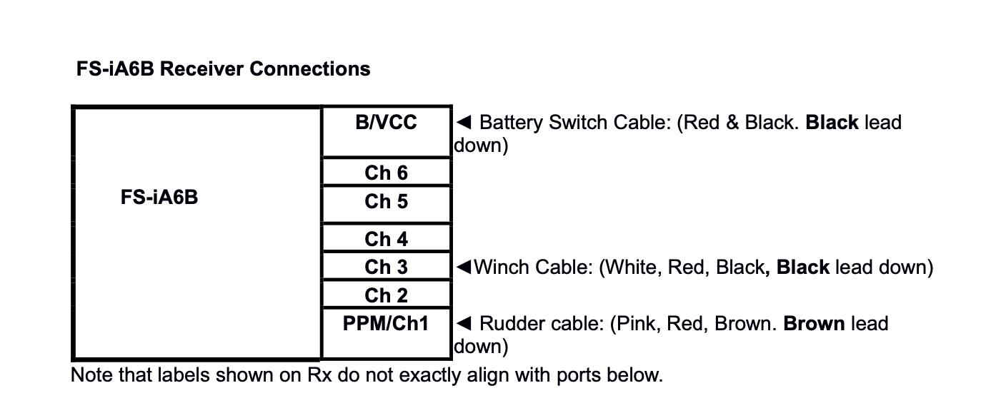
- The supplied Rx from HWH is the FS-iA6B with 7 ports and for neatness the three cables (battery switch, rudder and sail winch) plug-in horizontally from the end with the black/brown cable on the bottom. A FS-iA6 Rx is available and has the same functionality but the seven ports are arranged vertically with exposed pins. Depends how you want to arrange cabling.
- The iA6A is a lightweight receiver not suitable for a marine environment.
Instruction Manual
- A 32-page Instruction Manual is available from the web. Search “FlySky FS-i6 manual”.
- These notes should be read alongside the manual which is incomplete; some functionality is not explained. I have given my interpretation, but this may be inaccurate and if I err, please let me know.
- There are several of videos about the FlySky system used with RC yachts available on YouTube. Most others relate to control of model aircraft. Search on “FS-i6/rc yachts”.
- Version 2 1 1 July 2021
Waterproofing
- The Tx should not be used in the rain without a waterproof muff. Neither should the Rx. Mount as high as possible in the hull and keep the inside of the hull dry.
Switching Sequence
- Having assured the user there is no risk of interference from another radio frequency source, the maker recommends that a particular switching sequence be observed, which is: Tx ON, Rx ON: Rx OFF, Tx OFF.
- Additionally, when switching on, if switches or sticks are not in their correct position, screen and audible warnings will be activated. If however, sails have been rigged, after the Tx is switched ON, return the winch stick to a mid-range postilion before switching on Rx. This will prevent possible damage to sheets, sheet pulley or winch servo overload if sheets have been set too tight.
FlySky Operational Range
- The operational range of the FS-i6 is dependent on the condition of batteries and the orientation of both Rx antenna and how the Tx is held. The Rx has two antenna that should be mounted at a right angle on the underside of the hull or as high as possible. Unless there is electro-magnetic interference, or signal attenuation from metal yacht masts, range should never be a limiting factor in DF65 racing. Line-of-sight transmission is important at all times. Most sources quote a range of 300- 400m, but the system has been shown controlling a drone out to 2.3 km.
LCD Brightness
- LCD brightness can be controlled using System setup/LCD brightness. Might be useful when operating in bright sunlight.
Screen Saver
- If the Tx is not used for a short period of time the screen brightness will fade and an audible alarm will sound. The alarm can be switched off and the brightness restored by pressing any button. This can be changed by upgrading the software. Search YouTube for “FlySkyi6 Upgrade” videos.
Binding
- As explained above, each Tx has a unique ID, and the slave Rx must be programmed to process only those signals from the master transmitter.
The maker advises the supplied Tx/Rx combination is already “bound” but you may wish to operate two or more Rx from the one Tx in different boats. Hence the need for further “binding.” To bind a second Rx, you must first select a new model no. This is explained below. - Both the Instruction Manual and YouTube tutorials are clear enough as to how binding is done. Follow the sequence exactly.
With batteries loaded and Tx/Rx switched ON and before binding, a red LED on Rx will flash. This becomes steady when binding is complete. - Incidentally, the FlySky system provides for the control of up to 20 models which means you could have up to 20 DF65/95s (or aircraft) set-up independently and therefore each would require separate binding.
Binding Procedure
- Rx should be adjacent Tx
- Insert battery in Tx but do not switch on
- Insert binding cable into B/VCC port on Rx
- Insert Rx battery into any port (Ch1-Ch6). Red LED will flash indicating the Rx is not bound
- Hold down BIND KEY on Tx and switch on Tx – labelled POWER
- Release BIND KEY when binding is complete. The Red LED will remain steady
- Switch off both devices
- Remove the binding cable.
- Remove Rx battery lead and insert in Rx B/VCC port
- Switch on both devices in the correct sequence. Red LED will be steady.
Number of Models
- Additional Rx can be purchased and assigned a new model number using System setup/Model select. The binding procedure must follow for each new model number. The model can then begiven its own name and be loaded with its own unique settings.
- The system has the ability to be used to control up to 20 different models or in our case 20 different sail boats. Theoretically these Rx, each with their own settings, could be swapped in a boat, one Rx with its unique settings for each set of wind/wave conditions say. A lot of trouble for questionable gain. More likely each Rx could be mounted in a different boat each with a different rig.
Settings – General
- FS-i6 Tx has six channels and therefore offers six controls that presumably are required to operate a quad copter. Only two are required for the DF65 – to control rudder and sail winch. These two controls are variously referred to as the gimbals, control sticks or stalks. Most sailors use the left- hand stick (North-South) to control the winch and the right-hand stick (East-West) to control the rudder. These can be reversed using the Sticks mode in System setup menu. Additionally, the rudder control can be reversed so that it operates like a tiller. Select Ch 1 (rudder) and Reverse in menu.
There are four buttons on the Tx that are used to navigate through the menu and establish winch and rudder settings. The menu is arranged in a hierarchical structure. The four buttons and their function are:
OK CANCEL
UP DOWN
- It is helpful to navigate through the menu to become familiar with the use of the buttons and the range of settings.
- Use a Model No. that is not in use. Alternatively, Exit the screen with a short CANCEL to ensure any changes made are not saved. A long CANCEL will save the changes.
- Press to activate the displayed screen so that setting changes can be made. To select MENU a long OK is required.
- Short CANCEL to cancel any changes and exit the screen. Default screen will be the screen at the next level. Hold the CANCEL button for a longer period of time to save any changes to the current setting/s.
- Change the displayed or selected parameter upwards
- Change the displayed or selected parameter downwards
FlySky Menu
- The MENUs are selected by switching on Power and holding down OK. Two choices become available: System setup and Functions setup. Toggle between these using UP/DOWN buttons. Exit progressively to main display at any time by Short CANCEL. Changes made at any point are saved by Long CANCEL i.e., holding down CANCEL button.
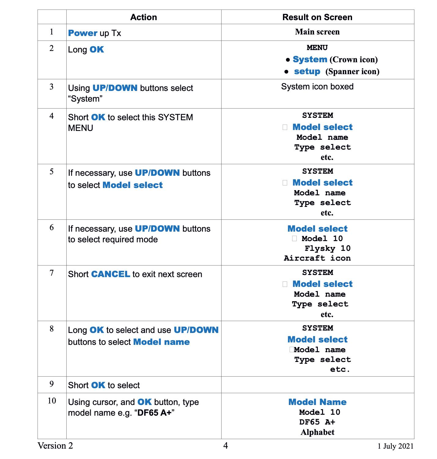
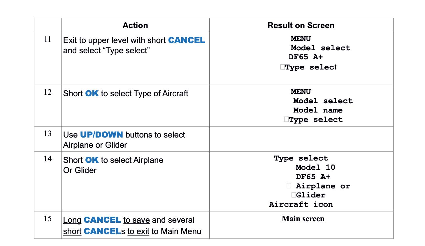
Selecting Model
- The example below shows the steps required to assign your DF65 A+ rig to Model 10 in FS-i6
Tx Battery
- For convenience use four 1.2v NiMH 2500mAh AA rechargeable cells giving a nominal 4.8v output when fully charged as an alternative to four 1.5v AA alkaline no-rechargeable cells. Because of a higher voltage it is acknowledged the latter provide more battery energy. Both have similar capacity in terms of mAh.
- When the recommended rechargeable NiMH cell is used, the voltage shown on the LCD screen would be typically Tx.V1:4.8v. Additionally the number of bars in a screen battery icon provides a quick visual reference. Note that the Tx Product Specification shows a power source of 4×1.5v AA Alkaline cells. Thus, when 4×1.2v NiMH cells are used the visual indication shows the reduced voltage i.e., fewer bars. The Tx battery voltage does not have to be set and there are no alarms available.
- It is strongly recommended that Tx battery be recharged after every outing.
Rx Battery
- Use a 2S (meaning 2 cells in series) 850mAh LiFe (LiFePO4) rechargeable battery with a nominal output of 6.6v (2×3.3v) when fully charged.
The DF65 Class Rules require a minimum Rx battery weight of 45g. Glue a washer or coin to the battery to bring it up to the minimum weight, if required. - The battery is usually mounted on the keel box with Velcro, and this will require a 15cm battery extension cable. Since there are two cells in series it is important the charger has the capability to give a balanced charge.
- Using System setup/Rx Setup/Rx Battery the FlySky6 allows the user to setup the following Rx battery voltages:
High: If LiFe battery is used, set to 6.6v. The Rx battery charge status will be reflected in the number of bars shown in the battery icon. This is a quick reference guide to the battery condition. The actual Rx voltage will also be shown digitally in the pane below. - Alarm: Set this to a voltage at which you would like to initiate an audible low battery voltage alarm, say 5.2v. Time to recover boat and replace battery.
Low: Set this to a voltage 5.0v. Anything less than this may cause loss of signal and boat control. - It is strongly recommended that the Rx battery be recharged after every outing.
RXL Pane
- The lower part of the LCD display shows the RXL pane which shows: IntV1:6.6v (Rx voltage from an Internal source)
Tx.V1: 4.8v (Tx voltage)
Signal Strength
- A typical reading is Err1:1%. The manual gives no details of what this means, but assume the higher the percentage number, the weaker the signal strength.
Failsafe
- Use System setup/Rx Setup/Failsafe to set the fail-safe setting when control is lost. This is a useful function to aid physical recovery of the boat. Set a permanent rudder deflection and eased sheets when there is a Rx battery failure, so the boat does not sail over the horizon.
Setting Rudder End Points
- A rudder throw of no more than 35 degrees is recommended to prevent stalling.
Select Function setup/Endpoints/Ch1 on Tx. Position hull so that physical mid-point and 35 deg. markings can be seen. Place steering stalk fully to starboard and using Up/Down controls to move rudder until aligned with 35 deg. mark. - Repeat for port. If the display reaches the maximum setting of 120 % before the 35-deg. mark is reached, then an increased rudder throw can be achieved by repositioning the connection point on the rudder arm towards the rudder fulcrum. The existing hole on the arm will have to be enlarged to accomplish this. It may be necessary to bend the connection rod to ensure it does not come in contact with the hull opening. The bellows may have to be temporarily removed to check this.
Setting Sail Winch End Points
- The winch line travel should be about 115mm. Change the number of turns on the drum to locate the main sheet attachment point at the back of the main hatch opening when fully sheeted in. Alternatively, undo the retaining screw on the winch drum and rotate in the desired direction. Slightly ease bowsies to ensure winch servo does not become overloaded, then Power-up, and sheet-in. Set the close-hauled position for both booms using their bowsies. Hold the hull vertically and ensure both booms fall under gravity. The fully eased point of both booms can be adjusted using Function setup/Endpoints/Ch3/Up-Down so that the main is at about 80 deg. and jib about 85 deg. In very windy conditions it may be appropriate to reduce the sail load to prevent nosediving by either easing both booms well beyond their normal settings or haul them in. This can be done by manual winch control or using SwA to invoke Sports mode. See later explanation.
Rudder Mid-Point Trim and Weather Helm
- It is not uncommon for the DF65 to sail to windward perfectly balanced (i.e., no rudder adjustment necessary) on one tack but to have a marked tendency to round-up on the other tack i.e., weather helm. This may be due to asymmetrical sheet settings and this should be checked, particularly the position of main sheet bridle on both tacks. It may also be due to the rudder being slightly off centre. This mid-point can be reset during racing by the rudder trim tab below the stick. When used, the audible tone indicates the direction of movement and the mid position. Alternatively, when not racing the rudder mid-point can be set using Functions setup/Subtrim/Ch 1 and the UP/DOWN buttons.
Rudder Movement – Rate
- In its factory setting, rudder movements are proportional or if you like, linear. A 50% movement of the stick to the right will result in a 50% movement of the rudder to the right, within the pre-set range.
- There are two ways of controlling the relationship between stick movement and rudder movement. The first is Rate, the other is Expo. They can be used alone or together. The impact of the setting is shown graphically in the LCD display.
- When Rate is used, a default setting of 100 will result in a full rudder throw. So, if the End point has been set at 35 deg. a full stick movement will result in a rudder movement of 35 deg. If a rate of 50 is used the rudder will move 35/2 or 17.5 deg. A rate of 50 and a 50% stick movement will result in a rudder movement of 0.5×0.5×35 = 9 deg. In effect, use Rate to de-sensitise stick movement in a linear way over the entire stick range. This can be useful when running downwind in strong winds, when even very slight rudder movements can have a dramatic effect on direction.
Rudder Movement – Expo (exponential)
- Expo is the other way of controlling the relationship between stick and rudder. Rate and Expo can both be used to control rudder movement, either singularly or combined. A second set of Rate/Expo settings can be use using Switch A (SWA) to invoke the Sports mode. More later.
With the use of Expo, the stick/rudder relationship changes from linear to one of a theoretically infinite number of exponential curves. For example, with Expo, a 50% stick movement to the right (or left) might result in only a 30% rudder movement – depends on the Expo setting. More rudder movement leads to proportionally higher response. - The extent of Expo applied is a matter of personal preference.
So, both Rate and Expo alter the default linear curve to one that either is less sensitive (positive expo) or more likely, more sensitive (negative expo) around the middle range. When using Expo, a typical starting point might be 30%. – depends on whether Rate is also used.
Rudder Movement Using Sport mode
- Use Switch A (SWA) to invoke the Sports mode to provide a second Rate/Expo setting. Only one set of End points can be used.
- How to Set Dual rate/Exp. For Alternative Rudder Control
- Power-up Tx/Rx
- Select model number as described above
- Using the Function setup menu, and short OK, index through to Dual rate/expo. Select with OK
- Short OK and if necessary, index to Ch1 (Rudder is selected)
- Throw Switch A (down) and Sport will be displayed
- Set-up Rate using Up/Down buttons. Index to Expo and again using Up/Down buttons select an Expo setting.
- Long CANCEL to save.
- Experimentation on the water should give an indication of the optimal rudder settings for Sport mode. Depends on its intended use.
Control of Winch in a Gust – Use of Throttle curve
- In the discussion above it was suggested that the most appropriate response in a gust is to ease sheets rather than use the rudder to counter the inevitable rounding-up. Of course, with fine motor skills, sheets can be fractionally eased at any time however it is suggested that a desensitised winch may be appropriate. This can be set-up using Throttle ease and Switch B (SWB). The curve should be not dissimilar to that used in the Rudder Sports mode. At Position 1 I have used 8%.
Back Up of Settings
- When using FlySky it is very easy to initiate system changes that don’t work and to then forget what has been changed.
- It is possible to either reset model settings using System setup/Model reset (Manual 7.4) or reset factory settings using System setup/Factory reset (Manual 7.12). The manual does not make clear what model setting is being reset.
- Perhaps a safer way would be to establish a dummy model using a unique model number and name. In the event or losing or corrupting the working model the back-up version could be copied to it using the Model Copy function described below.
Model Copy
- This function can be used to copy settings from one model to another. Any settings on the target model will be over-written.
To copy, Model 3 to Model 4 say, ensure Model 3 has been selected. This becomes the source model. - Select System setup/ Model copy
Select Target model and long CANCEL to save, then several short CANCELs to return to main screen.
Check settings on target model
Model Reset
- As the Manual says “This function will reset selected model settings to default but does not make clear what these default settings are.
The other models will not be affected. May be useful when a set-up is going nowhere and needs a fresh start.
Other FlySky Functions
- The FlySky system provides the rich functionality required for model aircraft and many features have no relevance to RC yacht racing. Not described here are Model name, Sticks mode (useful for changing from wheel operation to tiller operation), Reverse stick operation for left-handed sailors, Display (mid position and end points of all channels) and Sub trim. Refer Manual for more details.
Advanced Settings
- There is a “secret” Factory Setting Menu for experienced users. It is accessed by holding both sticks down at 45 degrees to the left i.e., SW before turning Tx on. The menu options are not discussed here, and more information is available by searching YouTube videos.
Disclaimer
- The Dual Rate features of the FlySky system have been described to highlight the available functionality. It does not follow they should be used. Moreover, some of the suggested setting are nothing more than that. Personal preference and experience are the best guide. I’d like to draw on that experience and over time I’m sure the best techniques and settings will evolve.
- I’m mindful of my experience with a compass on a Laser; when first used, I spent an inordinate amount of time watching the compass and far too little time watching the big picture i.e., getting my head out of the boat.
So, any speed gain made by using say Throttle curve in gusts during the race may all be lost in one bad mark rounding. - Concentrate on the important things first.
All will become clear over time as gifted sailors develop and refine what is fast for this class and provide feedback to the plodders.
David Flakelar
Questions and feedback would be very welcome. Email preferred dfflakelar@tpg.com.au Mob +61 404 829 414 or +61 2 9412 1742.
Version 2 8 1 July 2021
Appendix
Discussion on Weather Helm, Rudder Use and Starting a Race
Weather Helm
- These musings are meant to provide some background to the set-up of the DF65 winch and rudder using the FlySky system.
When racing, ideally, in steady-state conditions, we want the boat to track in a straight line particularly to windward with nil or only slight weather helm. If there is too much the boat will round-up and go into irons. - There are a number of measures theoretically possible to achieve balance:
- Constant and skilful rudder movement will provide straight line tracking however rudder movement is slow as the rudder when used provides a greater projected surface area in the direction of travel. It acts a bit like a brake.
- Mast rake by adjusting deck plate (the movement fore’n’aft can swing the top of the mast through 100mm), forestay and backstay tension.
- By these adjustments, the sail’s combined Centre of Effort (CE) can be moved fore and aft relative to the foil’s Centre of Lateral Resistance (CLR).
- By this we are essentially controlling the couple between these two forces.
- There is plenty of reading on the internet and elsewhere about this and won’t be repeated here. Generally, a small amount of weather helm is safer, and it is desirable to provide a bit of feedback to the helmsman otherwise the steering will feel dead.
- The latter does not apply to RC yachting.
- There is no known easy way of setting up optimal mast rake except by trial-and-error. The recommended measurement from a reference point on the upper mast to a point on the deck is about all there is. This method is a guide only and not very accurate. See Soch Sails DF65 Rig Tuning Guide.
-
Changing the CLR by lifting the centreboard/keel (impossible with DF65)
Reduce the power of mainsail by easing main sheet (more of this later), flattening foot or ease boom vang to soften leech (i.e., spill more wind from back of sail)
Reef main
- Increase power of jib by moving its CE forward and thus moving the entire rig CE forward. In an RC yacht a bit of weather helm is desirable, not for feel, but for another reason. When moving through the water the foils provide lift. This is analogous to the wing (foil) on an aircraft, particularly a glider. The downward gravitational force of the glider is balanced or counter-acted by the lift provided by the wing. One approach with DF65s might be to use the Trim tab referred to earlier and this might be a quick fix on one tack however it may have to be removed or re-applied on the other tack. There is no known way that an RC yacht can be provided with an offset rudder to provide the required minimal amount of rudder on both tacks.
The only way an RC yacht can move in a straight is by the accurate alignment of CLR and CE. However, any particular setting is only good for a particular set of wind and wave conditions. And may only be good for a particular tack.
In a wind gust these balanced forces become out-of-balance. The wind force on the sails increases with the square of the wind velocity but the counteracting force from velocity of water over the foils does not increase because in the instant the gust hits the boat speed has not increased and the boat rounds up. - The second impact of a gust is to heel the boat. The underwater shape of the hull changes from one that is symmetrical (when mast is vertical) to one where the line of least resistance is for the hull to move to weather. So, to counter the boat rounding-up, rudder is used to force the bow down. But as the hull heals the rudder has less effective area in the direction of travel and increasingly rudder has to be used. Any rudder movement slows the boat because of Newtons First law and the greater the rudder movement the greater the impact on speed. In short, any rudder movement is slow.
- The other means of countering the effect of a gust is to ease the sheets for the duration of the gust and a way of doing this is by a Throttle curve set-up using Switch B – Winch Control. It is
Version 2 9 1 July 2021
acknowledged that the sheets can be eased manually at any time. But use of SwB might just make it easier and more consistent.
Also, in a gust the apparent wind moves aft and as we have suggested, the impact on heeling-over and rounding-up can be minimised by easing sheets and increasing velocity. However, this is not the only possible response. Theoretically one could remain close-hauled and benefit from this velocity lift by sailing a slightly higher course. In dinghies, this is often possible by hiking harder and thus keeping the hull flat. - The recommended response to a wind gust is to slightly ease sheets although this needs to be contested.
No recommendation is made regarding taking the velocity lift and I would welcome feedback for further dissemination.
Rudder Use
- If during the starting sequence or when racing in a variable wind, and the boat is above close-hauled and either stationery or moving slowly, like a dinghy, it is possible that by sculling, she may be brought down to a close-hauled course. This does not violate RRS 42 Propulsion. See RRS 42.3 (d). That is, if the hull lies above close-hauled on the Port tack, by moving the rudder stick to the right and releasing so that the spring loading moves it to the centre neutral position, the scull may force the bow down to close-hauled.
- This suggests the rudder End points setting may have to be greater than that required for normal steering. This cannot be done using SW A in Sport mode. There can only be one set of end points. It is essential to have a physical mid rudder reference point on the underside of hull so that before launching one can determine whether the rudder is physically aligned fore-and-aft. To establish this neutral rudder reference point, remove rudder and turn the hull upside down. Carefully align a straight edge between centre of keel and centre of rudder post opening. Using a fine permanent marker, draw a short line aft of the rudder trailing edge position. This will be a reference for a neutral rudder.
- Assuming a 35 degrees rudder throw say, and using a protractor, mark the position of the trailing edge of rudder when helm is hard over – both tacks.
If there is any rudder slop, insert a short length of rigging line into the rudder post hole and trim excess later. Replace rudder and secure after carefully aligning with neutral helm marker. Ensure rudder moves freely.
Starting a Race
- There are fundamentally two ways of starting in a yacht race.
Displacement yachts will usually start their approach coming from distance because their inherent design and weight means they cannot easily be parked and subsequently accelerated away. The primary skills are to pick the right lane, at the right end, (consistent with line bias and whether the right, or middle or left-hand side of the course is likely to be favoured) and judge the speed of advance on distance so that the boat is at speed, in clear air, just behind the line when the gun goes. Simple.
The start of a dinghy race is usually fundamentally different. In say a quality Laser fleet, once the position on the line is determined, the boat is “parked” about one boat length back from the line and held in position by mainsail trim, so the leech just catches the wind. This, together with judicious sculling with the rudder, the dinghy can be parked so as to not move down the line onto other boats to leeward. Weather boat keep clear!
The process is;
– about n seconds from the start, where n will depend on the type of boat and how well it accelerates, simultaneously quickly sheet-on,
– hike to keep the boat flat, and
– as the boat accelerates, pull-away to close hauled.
This procedure is preferred to the keel boat type start because the need to judge time on distance is minimised.
It is not known which is best for the DF65? Maybe a mixture of both?
Version 2 10 1 July 2021
-
28 September 2022 at 16:05 #12386
Thank you!!
-
28 September 2022 at 16:23 #12387
You are most welcome Pete.
-
-
-
AuthorPosts
- You must be logged in to reply to this topic.